
Sheet Metal Defects and Solutions – Part II
Continuing from the first blog, the second part of this two-blog series will continue to discuss defects arising from common fabrication processes – in this case, metal cutting/shearing and stamping – and how to ensure that these issues are ironed out as part of overall effort to ensure that the end product is of the highest quality. As we will see going forward, there are some common themes which give rise to imperfections during the manufacturing process. These defects can be caused by incorrect material choice, poor tooling and improper operating procedures among other reasons. Let’s dive in and have a closer look at this fascinating topic.
Cutting/Shearing Defects and Solutions
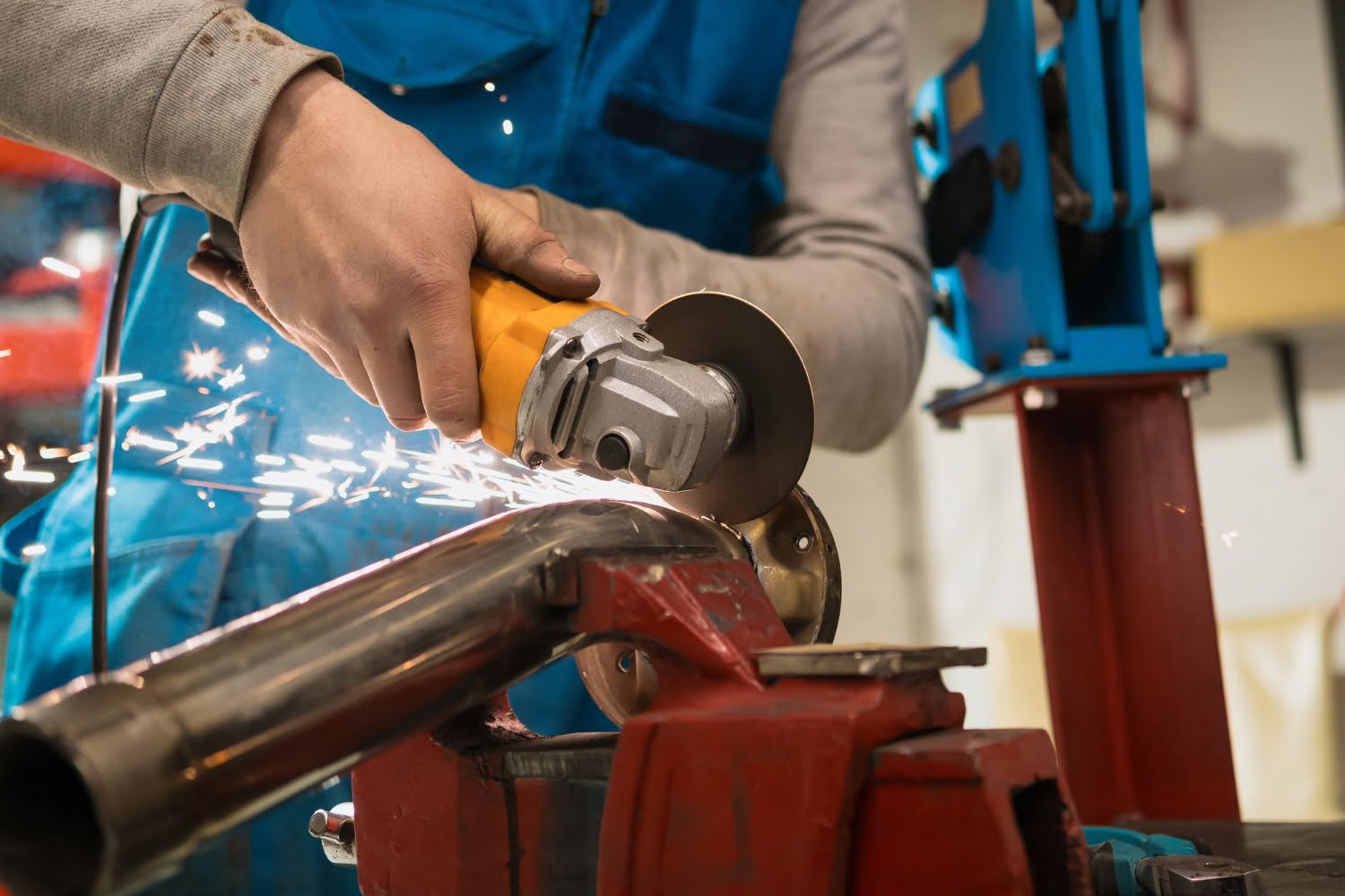
Sheet metal cutting refers to the application of a significant force on the sheet which eventually causes it to break into parts. The most common method of cutting is by shearing, in which a shearing force greater than the ultimate shear strength of the material is applied, causing it to fail and separate at that location.
Burred and Deformed Edges – Burred edges are sharp, uneven metal pieces that remain attached to a sheared metal workpiece. They usually arise due to blunt blades, or improper positioning thereof. Similarly, deformed edges are formed due to faulty clamp pressures, in addition to the improper positioning of blades. To prevent this, the shear machine’s manual can be referred to obtain the correct clearance and clamp pressure according to the material type and thickness.
Twisting – After completing a shearing process, the metal may have experienced some twisting along its axis. This is caused by cutting too narrow strips or using the incorrect rake angle. This can be avoided by adjusting the rake angle depending on the sheet metal’s properties, geometry, and cutting parameters.
Cambering – Cambering is observed when the sheet metal workpiece has a varying thickness along its width. This occurs when it moves in a horizontal direction, but without twisting or lifting along its edges. The result is a concave, convex, and triangular-shaped metal. This defect can be minimized early on by shifting the direction of the metal grains, and by changing the rake angle.
Stamping Defects and Solutions
The sheet metal stamping process is a cold-forming steel fabrication process where a die is used on a press machine to punch an impression on a metallic blank shape, thus forming plastic deformation. This process may also be accompanied by other forming tools to obtain a completed piece or as an intermediate step.
Splits – Sometimes when the metal layers are pushed past their workability limits, they start to thin until the flat layer tears along the weakest area. Such defects are known as ‘necking’ or ‘splitting’ in the sheet metal stamping process. To ensure this does not occur, forming simulation software should be used to analyze the sheet before the operation is started.
Wrinkles – When the compressive strain conditions applied by the processing equipment push the sheet metal upon itself, the linear force is crushed inwards until a wrinkled flange is obtained and the internal geometry is damaged. Such defects can be countered by stretching or drawing the sheets instead of forming them.
Springback – When the bend radius falls below the set value imposed by the heat induction bending equipment, the desired shape is not achieved. This is known as spring back, or final part deviation due to an incorrect process. To correct these defects, it is recommended to include an overbend or overcompensation adjustment.
Signing Off

Apart from sheet metal forming processes, other common errors can occur during the manufacturing process. For instance, some of the common defects include surface scratches, contamination, dents, and pinholes. Sometimes, controlling these defects can be difficult, and often requires special attention during the process. However, it is commonly agreed that in case of defects, reworking instead of replacing is the way to go – as it saves on two major metrics, cost and time!


