
Tipping and Bowing of Metal Parts
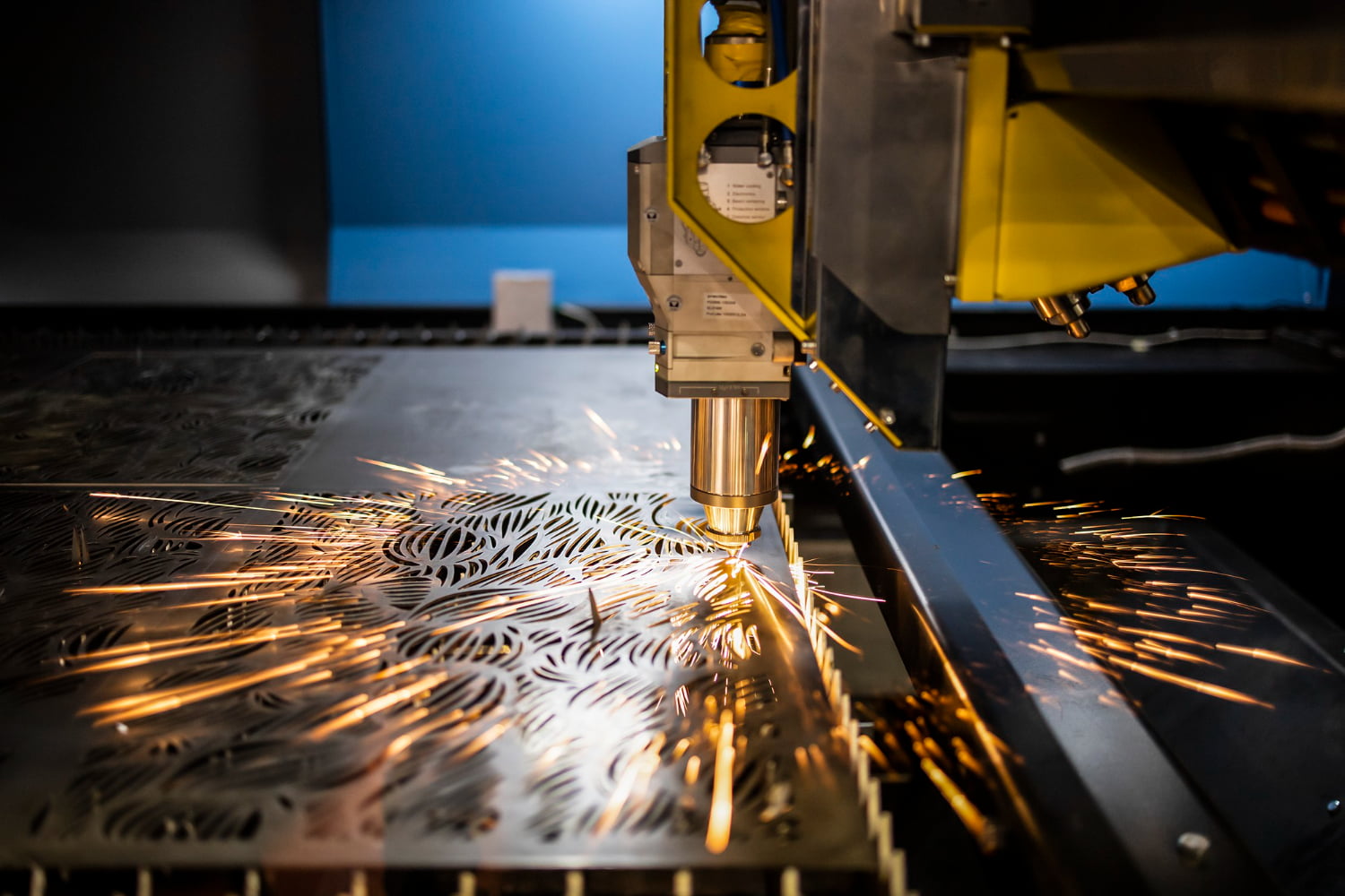
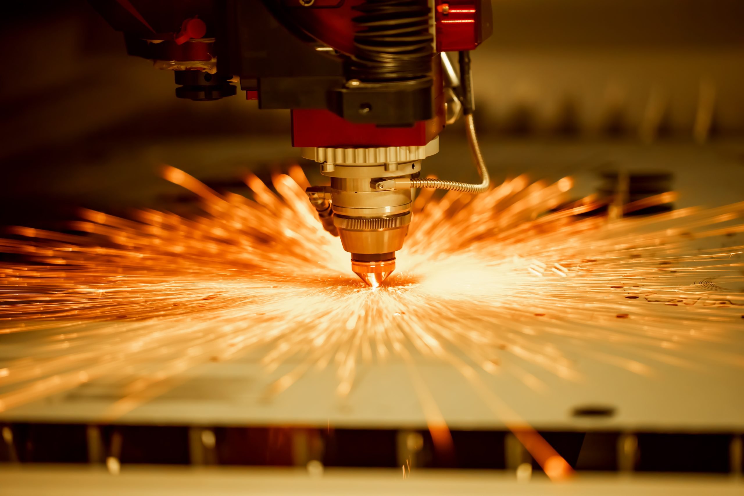
It is well-known that the primary cutting operation at most metal fabricators is performed by the fiber laser. This has made steel laser cutting very productive – until a part tips and causes a head to stop or crash. This can harm the productivity and cosmetic value of metal forming and increase the expenditure required to create the final product. This blog will look to explore this topic in more detail and also cover the subject of tabbing.
Reasons for Tip and Bow
Years ago, many machine providers and software vendors focused on transitioning operators from punch presses to the flying-optic lasers. Because the punch moves the sheet, everything needs to be tabbed in place, at least until they are evacuated down a chute or lifted by suction cups on an automated part removal system. Otherwise, parts do not fall out of a nest until operators snap or shake them out. When shops jumped to the flying optic lasers, sheets no longer moved, and many parts that were punched with microtabs no longer needed them. Of course, such lasers introduced a new variable: the slat position.
Slats generally are placed 2 to 3 inches apart, depending on the model of the machine. So, if a part (or slug from an internal feature) has at least one dimension less than 6 inches, it has the potential to tip. Most slats consist of tips or “teeth” that support the work. Certain part geometries could end up tipping into the “V” of the slat. Smaller parts can tip, but larger parts—especially those that are long and thin—can bow upward and throw a wrench into process stability of products such as pressure vessels. Material touted as being “laser flat” ideally should have equalized stresses such that, when a part is cut in the optimal way (to control the effects of heat, for instance), it does not bow.
Ripple Effects of Tabbing
These days, software can automatically detect and rotate parts so that the longest dimension is oriented perpendicular to the slats. Programmers also can set different tabbing strategies for different part sizes; a very small part might require just one tab, while larger parts up to a certain dimension require progressively more. Beyond a certain dimension, software will not place any tab at all. Tab placement can vary depending on the job requirements and the best practices at a particular structural steel fabrication company. For instance, some operations might choose to tab parts directly on the corners, while others prefer tabs on straight edges and, if a corner needs something for stability, a tab can be put several thousands of an inch away from the actual corner. It all depends on what benefits downstream operations and the part’s ultimate fit and function. Tab geometry can change depending on material thickness and grade, but it can also change based on what operations a part will undergo downstream. Those tab geometries affect how they break away from the part. At the laser offloading area, operators might shake parts out of a nest before running them through a flat-part deburring machine. Microtabs typically leave a burr on the part and a divot in the skeleton. This assumes that a fabricator will want to deburr the piece to create a perfectly flat edge.
Closing Statement

It needs to be understood that every machine part does not need a perfectly flat edge. For edges hidden within an assembly or covered by a weld, shops might choose to skip deburring and send the parts directly to forming. This may help in ensuring that parts do not form tips and bows, however that would also depend on other variables like the cut path strategy, nesting etc. In essence, it is possible to manage material from forming tips and bows – however there needs to be a greater understanding of the laser cutting process to manage this phenomenon.